FCR013 is a communicative controller of heating and cooling panels and an EC (electronic commutator) motors or a VAV (variable air volume) damper. It measures temperature in the room using a room unit and it may either work autonomously, or be connected to a primary controller (MiniPLC/markPLC) or SCADA (RcWare Vision or any other SCADA able to act as Modbus master). As a room unit, UC013 is used.
- Individual room control for systems with heating and cooling panels and EC motors or VAV dampers
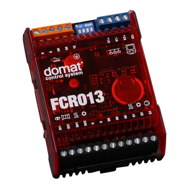
The controller communicates with a room unit UC013 over a dedicated bus (K2+, K2-). The room unit UC013 reads room temperature, setpoint correction by a knob, and operating status, which is selected by a short push of the button. Measured temperature range is 0 to +50 °C. Read and entered values are processed in a PI (temperature) control algorithm. On the output, there are analogue 0..10 V sequences to control the valve actuators and EC motors or VAV controller.
The binary input DI1 switches between Comfort and Standby operating modes. The DI2 switches to Off mode. The triac outputs DO1 and DO2 can be controlled over the bus as auxiliary outputs.
The controller incorporates real time clock with weekly scheduler (6 events per day). It switches between the Comfort, Precomfort, and Off operation modes. There is a binary presence input on the controller for access card reader, PIR sensor etc. Both NO and NC contact may be used, the selection follows in the configuration software. Each operation mode has separate setpoints for heating and cooling which are used as basis setpoints for setpoint calculation: to the basic setpoint, the manual setpoint correction is added, and the result is used as actual setpoint for heating or cooling. Three LEDs indicate correct function: green (PWR) – power OK, red (TX1) – transmit data to the building bus, and red (TX2) – transmit data to the room unit. On the top there are four DIP switches: K1 bus end, and init switch to set factory defaults (Modbus address 1, communication 9600 bps, N, 8, 1).
The controller communicates with the management system over RS485 bus with Modbus RTU and therefore can be used in many control systems. See the variable list (Modbus table) in a separate document Room units and controllers (http://domat-int.com/en/downloads/technical-documentation/modbustables). Another bus, K2, communicates with the room unit. To configure and commission the controller use ModComTool, which is free to download at http://domat-int.com/en/downloads/software.