FCR011 Communicative fancoil controller, 230 V AC

Fan coil controller, communicative

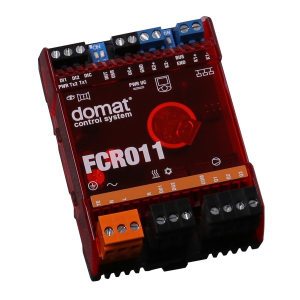
2 x DI (presence, window), 2 x DO triac 230 V AC for thermic valves (heating, cooling) , 3 x DO relay for three-stage fancoil 230 V AC, 1x Modbus slave / RS485 for SCADA/primary controller, 1x Modbus master / RS485 for UC010

Datasheet

FCR011 is a 230 V AC powered communicative fan coil controller (up to 3 fan stages, heating and cooling valves). It may either work autonomously, or be connected to a primary controller or SCADA (any SCADA able to act as Modbus master). As a room unit, UC010 is used. 
 
  • Individual room control for systems with 4 pipe fancoils 
  • Individual room control for systems with 2 pipe fancoils 
  • Individual room control for cooling fancoils and radiators 
  • Individual room control for heating convectors and cooling panels 
     
The controller communicates with a room unit on a dedicated bus (K2+, K2-). The room unit, which is powered from the main controller, reads room temperature, setpoint correction by a knob, and operating status, which is selected by a short push of the button or in the menu. Measured temperature range is -20 to +50 °C. Read and entered values are processed in a PI control algorithm. On the output there are PWM modulating sequences for triacs to control the thermic valves. 
 
The controllers operate in a non-aggressive environment. No maintenance is necessary. They are mounted with two screws on any flat surface, e.g. fan coil body, or installation board. The holds can be removed and controller could be fixed on DIN rail. (See Installation below.)
 
The controller incorporates real time clock with weekly scheduler (6 events per day). It switches between the Comfort, Precomfort, and Off operation modes. There are two digital inputs on the controller for presence sensor (access card reader, PIR sensor etc.) and for window contact or dew point sensor (switches to the Off mode).
 2 02/2017 Subject to technical changes. domat FCR011
Both NO and NC contact may be used, the selection follows in the configuration software. 
 
The fan stages are either controlled automatically (with control deviation, or rather PI controller output) or manually (if this function is enabled). Three LEDs indicate correct function: green (PWR) – power OK, red (TX1) – transmit data to the building bus, and red (TX2) – transmit data to the room unit. The controller further includes DIP switches for initialisation (bringing to factory defaults) and K1 bus termination.
 
The controller communicates with the management system over RS485 bus with Modbus RTU and therefore can be used in many control systems. See the variable list (Modbus table) in a separate document Room unit and controllers. (http://domat-int.com/en/downloads/technical-documentation/modbus-tables) Another bus, K2, communicates with the room unit. To configure and commission the unit use ModComTool, which is free to download at http://domat-int.com/en/downloads/software.